
Problem: When working with geospatial data, having the ability to integrate computer aided design drawing (CAD) files is very important. Many times designers produce CAD drawing files of their designs that are to scale but are not georeferneced and spatially accurate. This has become increasingly more important as designs are developed in model space and contribute to overall 3D virtual designs. Converting files between CAD and GIS and using GIS to georeference CAD line work is an essential skill for every GIS professional.
In this example North Carolina State University needed a database of all campus features such as campus roads, pedestrian routes, campus recreation and athletic areas, campus buildings and some natural resources that were already contained in a CAD drawing file. The GIS file geodatabase will allow NC State University to manage their future planning campus growth and ongoing operations and maintenance at existing facilities.
Analysis Procedure: To begin the process of converting the CAD information into the GIS file geodatabase data provided by NC State were reviewed. The data included a CAD drawing file (.dwg) which contained the following layers:
- streets (campus streets only: "Streets")
- sidewalks (campus only: "Walks - Sidewalks")
- streams / creeks (HINT Rocky Branch is the name of the main creek through campus: "Water - Rocky Branch")
- lakes / ponds ("Water - Lake")
- buildings (include campus only - existing AND future buildings: "Bldg - Existing" and "Bldg - Future")
- athletic fields ("Athetic Fields")
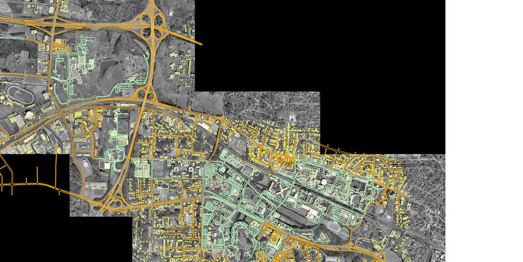
Also provided was an aerial image of the campus region which was in a multiresolution seamless image database (MrSID) format. The image and CAD files were reviewed to confirm the required layers needed for the file geodatabase for NC State were present.

Using esri ArcGIS 10.4.1 the aerial image was displayed and the CAD drawing file imported to overlay the image. The esri ArcGIS GeoReference tools were used to shift, rotate, and scale the CAD drawing. The drawing was also orientated over the aerial image by plotting two control points that align line work to edges of buildings or roads in the aerial image. These control points were placed at as great a distance from one another as possible. Using the control points the final georeferencing of the CAD drawing file took place. When complete a world file containing the coordinate extents for the CAD drawing was produced for use of the CAD file in other geospatial systems.
Once the CAD line work was spatially correct the needed layers from the CAD file were identified for the appropriate polyline or polygon GIS datatypes. Buildings, Athletic Fields and Lakes and Ponds were converted to polygons and sidewalks, streams, and streets were converted to polylines. These layers were identified and then exported directly to the new file geodatabase using the Export Data function.
Results: The outcome of the process produced a file geodatabase that included all of the layers identified by NC State above for use in their Campus Planning and Maintenance system.
Application & Reflection: Georefernecing aerial images and CAD files is an extremely important task for someone who is managing environmental data. Roadways and natural features such as rivers and lakes are good for using as points to georeference CAD layers.